UML diagrams vs. simulation in software design
 October 22, 2022
 2736 words
 13 minutes to read
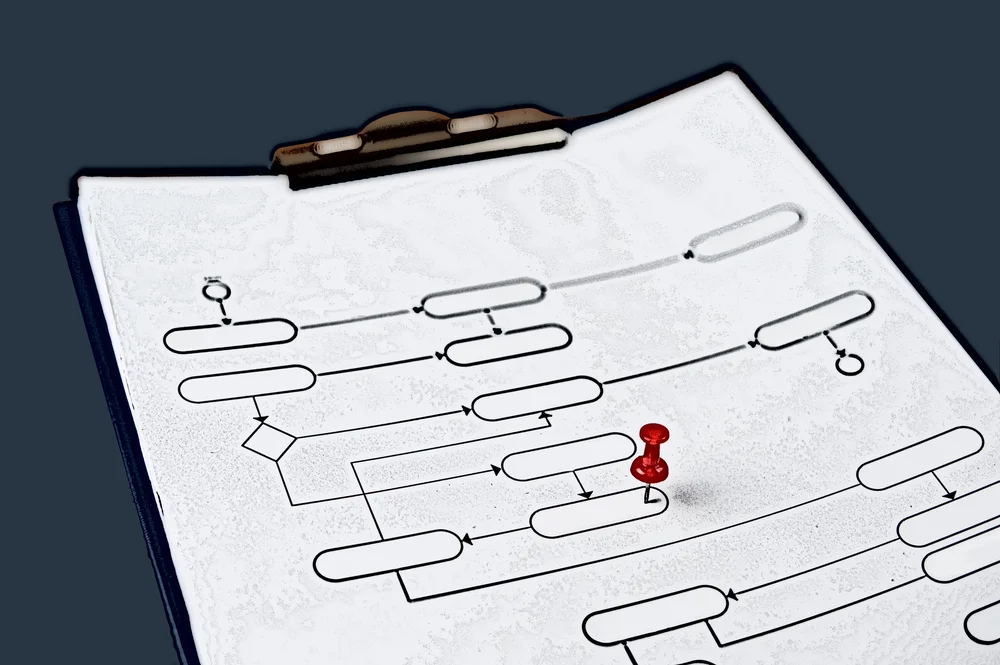
Software design is an invaluable tool in the early stages of software development. With software design, teams can flesh out the technical aspects of their projects, communicate their ideas to stakeholders, and build products that have business value.
Excellent software design is instrumental in the success of any software product, so it’s essential to get it right. Fortunately, any business can design top-notch software systems and applications in this day and age of tech. Software design is more manageable thanks to the vast range of available tools. What are these tools exactly, and how can they help you?
While there are many tools that teams can use to streamline software design, we will be talking about just two of them today – UML diagrams and simulation. Both can effectively enhance software design, but they are very distinct and not interchangeable.
We will cover their advantages and disadvantages to clarify how UML diagrams and simulation can improve software design and help you build better products. We will outline the best use cases for both.
What is software design?
Before we cover the differences between UML and simulation, let’s first define software design. An early stage of the software development lifecycle, software design is the process of defining and conceptualizing software solutions. Software design outlines the methods and tools developers will use to build a specific piece of software. The design also incorporates the technical specifications and constraints of the software.

Design is defined as both “the process of defining the architecture, components, interfaces, and other characteristics of a system or component” and “the result of [that] process” (ISO/IEC/IEEE, 2010, p. 100).
“Viewed as a process, software design is the software engineering life cycle activity in which software requirements are analyzed in order to produce a description of the software’s internal structure that will serve as the basis for its construction. A software design (the result) describes the software architecture—that is, how software is decomposed and organized into components—and the interfaces between those components. It should also describe the components at a level of detail that enables their construction.” (IEEE, 2014, p. 2-1)
Other informed professionals have weighed in on the definition as well:
- “Software design refers to issues, methods, strategies, presentation methods and patterns used to determine how to implement a component or a system” (Joint Task Force on Computing Curricula, IEEE Computer Society and Association for Computing Machinery, 2015, p. 32].* “Software design is the stage of software development, during which the specification is transformed into a structure suitable for implementation. Design training should cover both the design object and the process by which this object is created” (Carrington, 1998, p. 547).* "…software design [is] a systematic, intelligent process in which designers generate, evaluate, and specify concepts for a software system whose structure and function achieve clients’ objectives or users’ needs while satisfying a specified set of constraints" (Hu, 2013, p. 64).
Software design is related to software architecture but is not the same. Software architecture defines how the software will be built at a high level. Unlike software design, software architecture isn’t concerned with the technical details of the implementation. Instead, it defines the components of the software and outlines how they are supposed to interact with each other.
You could say that software architecture defines what will be constructed, while software design outlines how a software system will be constructed.
Teams can use toolsets like UML diagrams and simulation to facilitate and enhance software design. But while both techniques can improve software design, they achieve results in drastically different ways.
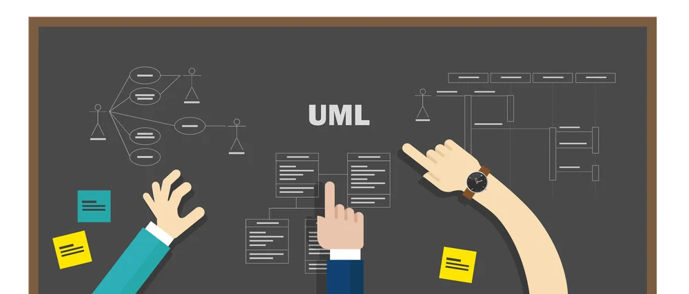
What is UML?
Managed by the Object Management Group (OMG) since 1997, the Unified Modeling Language, or UML, is a language for visualizing the operational flow of applications, systems, and processes. A key component of UML is its diagrams, which teams can use to visualize the design of their software systems, including their components, steps, dependencies, and interactions.
UML is flexible enough to model any software, hardware, and programming language combination. Designed with object-oriented applications, UML can integrate with object-oriented languages like C++ and Python. However, UML can also be used with other families of programming languages.
UML specifications define over a dozen diagram types broken down into three categories – structure diagrams, behavior diagrams, and interaction diagrams. The spec can be challenging for the novice using UML.
Structure diagrams emphasize static components in a system or application, primarily including:
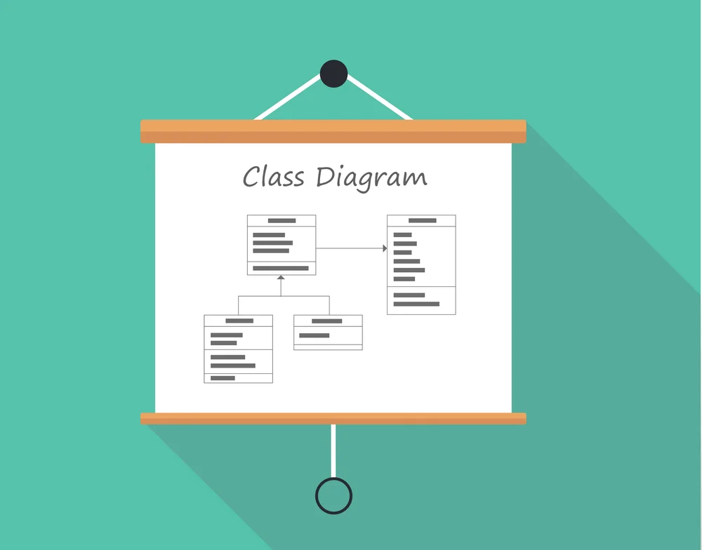
- Class Diagram,
- Object Diagram,
- Component Diagram,
- Composite Structure Diagram,
- Package Diagram, and
- Deployment Diagram.
Behavior diagrams describe the dynamic aspects between different system components, primarily including:
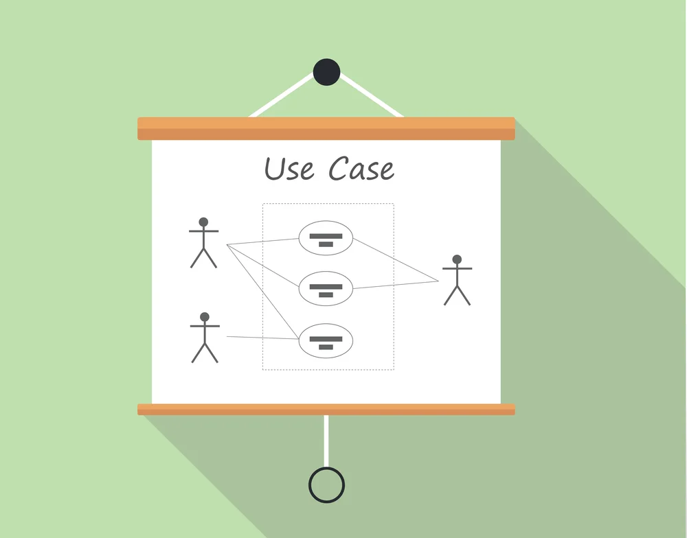
- Use Case Diagram (a potential requirements gathering methodology),
- Activity Diagram, and
- State Machine Diagram.
Interaction diagrams are derived from the more general Behavior Diagram and include:
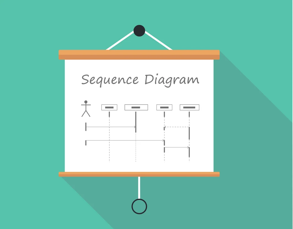
- Sequence Diagram,
- Communication Diagram,
- Timing Diagram, and
- Interaction Overview Diagram.
Some people mistakenly think that UML is a programming language – it is not. Instead, UML is a tool that can help software teams envision, define, and document their software products and systems.
While we will be considering UML from the software design standpoint, it’s not exclusive to the software industry. UML can benefit any process, system, or product that can be visualized through diagrams and plots.
How can UML enhance software design?
UML was conceived as a standardized toolset for software and application design. UML diagrams are equivalent to manufacturing, engineering, and architecture blueprints, and could be used as reference documents in software design.
While UML is primarily a visualization tool, the use cases of UML are numerous and aren’t limited to just visualizing software processes and workflows. Below are just some of the applications of UML in software design.
- Because UML is standardized, UML diagrams can be shared and reused across different teams and departments. Standardization can benefit large projects involving multiple teams that need to work with each other’s development artifacts.
- UML diagrams can be a powerful communication tool between software teams and stakeholders. Teams can use UML diagrams to introduce stakeholders to the operational workflow of their application without any daunting technical details or jargon.
- Teams can use UML diagrams to ensure that their software matches their specifications and expectations. There are tools on the market that can read and run UML diagrams to help software teams ascertain that their applications behave as expected. These tools essentially turn UML into simulations (which we’ll cover more in-depth below).
- Teams can use UML diagrams to generate application code automatically. To do this, teams can use specialized tools that convert UML diagrams into programming code. This code is often not perfect, but it can cover the application’s basics and help developers deliver their products to the market quicker.
- Teams can use UML diagrams to better understand how their applications work. Some UML tools can analyze programming code and turn it into UML diagrams. In this sense, UML diagrams can serve as a debugging and troubleshooting tool in software design.
What is simulation?
Simulation modeling is the process of creating a digital imitation of a real-world system or process. Simulation models capture a process from beginning to end and can show how it progresses through time.
Executing a simulation essentially means running a realistic digital copy of the target process on a computer. In other words, simulation is a way to perform experiments in a virtual environment.
Because simulation can realistically represent different processes, it can help researchers figure out how the simulated system will behave in the real world. The range of systems that simulation can accurately model is vast and includes continuous and discrete systems and even systems with complex interactions between their components.
Although simulation modeling aims to represent real-world systems faithfully, it is not necessarily 100% realistic. Realism is not only often unachievable but also unnecessary for many simulation studies. The team should strive to achieve sufficient realism and accuracy for your project and objectives – anything more than that would likely be a waste of time and money.
Simulation is highly data-driven. Simulation engineers need to collect vast amounts of data to run successful simulations. Not only that, but they also need to statistically analyze the data to be able to identify meaningful relationships between different variables. Furthermore, simulation studies require a strong understanding of the target process so that engineers can accurately double-check the results of their work.
An essential feature of simulation is that it can handle uncertainty. At a high level, uncertainty happens when you can’t collect enough data to represent the target system fully. Some percentage of uncertainty is always present in simulation studies – it can be extremely challenging or even impossible to collect all-encompassing data that would tick all the boxes.
To handle uncertainty, researchers use probability distributions. Based on special tests and assumptions about the statistical properties of the process in the real world, researchers can use probability distributions to fill in missing data points artificially. Thanks to statistics and probability, researchers can effectively draw insights even from incomplete sets of data.
How can simulation enhance software design?
At a high level, simulation teams can use simulation to assess:
- Product performance in the real world.
- Impact of different tweaks and changes on the product’s performance.
- Comparison of a new product or process compares to an existing one.
As far as software design is concerned, simulation can help teams predict the performance of their planned software systems in the real world. Through simulation, software teams can accelerate prototyping and gain more concrete insight into the real-world potential of their product. Among many other things, teams could potentially use simulation to roughly check:
- Effect of different UI layouts on user engagement and conversion rates.
- Efficiency and effectiveness of traffic spikes and the impacts of spikes on user experience.
- Elapsed time for support staff to process a complaint from a customer.
If we look a bit broader, simulation can tremendously benefit software delivery. Software teams can use simulation to help them plan their software development lifecycles (SDLCs). And perhaps more importantly, teams can use simulation to assess the impact of different tweaks and changes to their software delivery pipelines. For example, software delivery teams can use simulation to assess:
- Performance of a new software delivery pipeline relative to the existing one.
- Impact on an application’s time to market by adding one extra team member.
- Decrease time-to-market by reduction of the rate of bugs in code.
- Impact of automating specific steps in a software delivery pipeline, reducing completion time to minutes rather than hours or days.
Assuming that simulation modeling is set up and performed correctly, it is a safe and efficient way of testing software improvements and changes. Because simulation is done digitally on a computer, there’s no risk to the real-world system if the changes go wrong. Simulation engineers can make incremental tweaks to their models too - to quickly find the best combination of parameters for their software systems.
Simulation is also great for checking assumptions and ensuring a software system works correctly. In this sense, simulation enables teams to ascertain that they are building the right system and that it addresses the needs of end users.
UML vs simulation – what’s the difference?
UML and simulation might appear similar at first glance, but they work differently and pursue vastly different goals. To summarize the points from above, here’s how UML and simulation differ:
- UML is focused on the visual, static representation of a process. UML encompasses more of a planning function to help teams better understand the processes they are trying to analyze, change, or develop. Aside from that, UML can serve as a communication tool between technical staff and non-technical stakeholders. Some examples can be viewed here.
- Simulation is focused on the flow of a process in time. Simulation emphasizes the dynamics of a process under the influence of time or its environment. With simulation, businesses can check their assumptions and test the performance of their product, service, or process in a safe environment. Some examples can be viewed here.
Subsequently, simulation is more about how the process works rather than what it looks like visually. Simulation can be a powerful tool for predicting the performance of an application in the real world without deploying it in real-time. Nonetheless, simulation studies can be extremely challenging to implement for several reasons.
As far as software design is concerned, simulation is in its infancy, and not much research was executed into the benefits of simulation in software design. Not only that, but software design simulation requires a statistical understanding of your software’s flow. For example, if you wanted to assess how UI changes might affect conversion rates, you would need to have past statistical data on the conversion rates of different UI elements.
This brings us back to a simulation’s reliance on data, which is challenging. With enough high-quality data, you can probably simulate any and every aspect of software design. Without good data though, simulation cannot be realized effectively. The lack of high-quality data is the biggest obstacle to simulation and a reason why many teams might have to stick to UML diagrams for software design.
How can simulation and UML be combined?
Simulation or UML – which one is the right tool for software design? The team does not have to choose only one or the other. Both UML and simulation can be extremely useful in software design.
When used separately, the ideal use cases for UML and simulation would be as follows:
- UML diagrams are likely ideal when the goal is to understand a software system. While UML diagrams have their own challenges, they aren’t as data-heavy as simulation and are easier to set up.
- Simulation is likely ideal if a project’s goal is assessing the system’s performance and checking assumptions in a real-like environment. Simulation requires careful setup and plenty of data, but it’s miles ahead of UML diagrams when system dynamics are important. That said, even when system dynamics is the main focus, simulation isn’t always the best tool to use – sometimes, direct experimentation is quicker and cheaper.
UML and simulation can also be combined to enable teams to design more complete and high-quality software products. With UML, software teams can get a visual feel of what their software will do. As for simulation, it could be used as a prototyping tool to help teams predict the performance of their products or even entire software delivery pipelines.
A few case studies would help to illustrate how UML and simulations can be combined:
- DICE simulation: a tool for software performance assessment at the design stage (Bernardi, et al., 2022),
- Professional competencies of future software engineers in the software design: teaching techniques (Striuk and Semerikov, 2022, June), and
- A multicomponent distributed framework for smart production system modeling and simulation (Gorecki, et al., 2020).
Next steps
The team will require UML training unless you can hire previously credentialed or qualified UML specialists. We suggest training that combines a specific UML tool with your chosen methodology, ordinarily available from either the tool supplier or the methodologist. OMG can also provide some introductory training through its tutorials:
Alternatively, courses may be selected from an OMG directory. Trained UML specialists can become OMG-certified UML Professionals.
References:
Bernardi, S., Gómez, A., Merseguer, J., Perez-Palacin, D., & Requeno, J. I. (2022). DICE simulation: a tool for software performance assessment at the design stage. Automated Software Engineering, 29(1), 1-36.
Carrington, D. (1998). Teaching software design and testing. Conference Proceedings of the 28th Annual Frontiers in Education Conference-Moving from ‘Teacher-Centered’ to ‘Learner-Centered’ Education. Vol 2 (pp 547–550). https://doi.org/10.1109/FIE.1998.738732
Gorecki, S., Possik, J., Zacharewicz, G., Ducq, Y., & Perry, N. (2020). A multicomponent distributed framework for smart production system modeling and simulation. Sustainability, 12(17), 6969. doi:10.3390/su12176969.
Hu, C. (2013). The nature of software design and its teaching: an exposition. ACM Inroads, 4(2), 62-72.
ISO/IEC/IEEE. (2010). ISO/IEC/IEEE 24765:2010 Systems and Software Engineering—Vocabulary.
IEEE. (2014). SWEBOK-V3.0 - Guide Software Engineering Body of Knowledge. In P. Bourque and R. E. Fairley (Eds.) SWEBOK: A Project of the IEEE Computer Society. IEEE.
Joint Task Force on Computing Curricula, IEEE Computer Society and Association for Computing Machinery. (2015). Software Engineering 2014: Curriculum Guidelines for Undergraduate Degree Programs in Software Engineering (A Volume of the Computing Curricula Series). https://www.acm.org/binaries/content/assets/education/se2014.pdf
Striuk, A. M., & Semerikov, S. O. (2022, June). Professional competencies of future software engineers in the software design: teaching techniques. In Journal of Physics: Conference Series 2288(1), p. 012012. IOP Publishing.